In case of crosshead type engine the underside of the liner is separated from the crankcase by means of a diaphragm. This means that liner cannot be splash lubricated and a separate cylinder lubrication is necessary.
L.O. pumps for large 2-stroke crosshead engines are not engine driven , but are electric motor driven . Pumps are provided in duplicate and work in auto-standby mode .( i.e. failure of one pump or loss in L.O. pressure will automatically the standby pump , if auto standby mode is selected.)
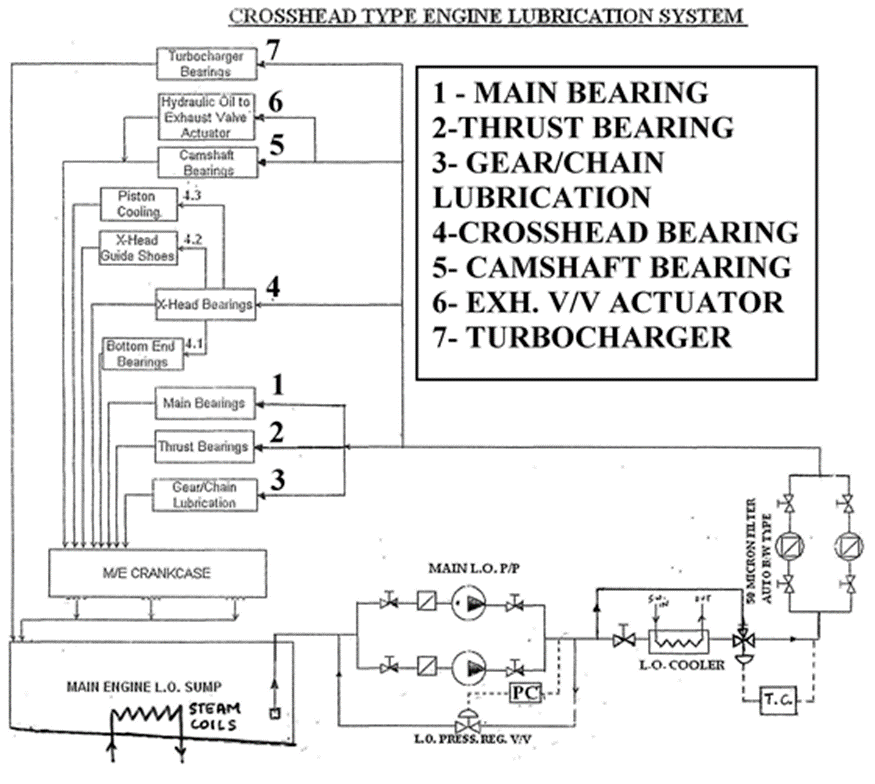
General Overview of Lubrication System
Lubricating oil (L.O.) pumps extract oil from the L.O. sump using suction filters. These filters in L.O. pumps usually contain magnets that capture metallic fragments arising from wear in various engine components. These fragments are rinsed off from the lubricated parts into the crankcase and eventually into the L.O. sump. When cleaning the suction filters, it is important to inspect the metallic debris accumulated on the magnets. A higher amount of debris suggests a higher rate of wear, while a lower amount indicates the opposite.
The pump's discharge is equipped with a pressure-regulating valve that automatically adjusts the pump's discharge pressure, regardless of the temperature of the lubricating oil (L.O.). When the L.O. temperature is low, it causes an increase in viscosity and resistance, leading to higher discharge pressure from the pump. A pressure sensor placed on the pump's discharge continuously monitors the pressure and sends signals to the pressure controller. If there is an increase in pressure, the pressure-regulating valve opens more to maintain the pressure at the desired level, and vice versa.
The lubricating oil (L.O.) then travels from the pump discharge to the L.O. cooler, which can be cooled using either sea water (S.W.) or fresh water (F.W.). The pressure on the L.O. side is always maintained at a higher level than the pressure of the cooling water to prevent any contamination of the L.O. in case there is a leakage in the tubes(in case of Shell and Tube type HX) or leakage in the gaskets(in case of plate type HX).
A temperature control valve is provided, which automatically regulates the temperature of the outlet for the lubricating oil (L.O.) from the cooler. In the event that the temperature of the L.O. outlet falls below the set value, the cooler bypass will open. Conversely, if the L.O. temperature exceeds the set value, the cooler bypass will close. This mechanism enables effective control of the L.O. temperature based on the predefined set value.
After the cooler, L.O. passes through a fine filter. The mesh size of this filter is about 30-50 microns. Duplicate filter is provided, so that filter can be cleaned during engine running without having to stop the engine.
Thereafter, oil goes to various places as shown in the above figure.
For gears case ( Sulzer & other engines) & chain case ( MAN B&W engines) L.O. spray nozzles are provided which spray pressurized L.O. directly onto the loaded portion of the meshing gears /chain-sprocket.
Oil is also supplied in the form of a spray to the tilting pad type thrust bearing, which is responsible for handling axial thrust. In the case of main propulsion engines, thrust bearings play a crucial role in transmitting axial propeller thrust to the ship's hull and the engine/thrust bearing foundation.
L.O. at same pressure of abt. 3 to 3.5 bar is supplied to crosshead bearing by means of TELESCOPIC PIPES in case of MAN B& W 2-stroke engines and other designs.
In case of Sulzer engines , the L.O. is first supplied to engine driven or separately driven Crosshead L.O. p/p ( all modern engines have electrical driven crosshead pumps). The crosshead pump develops high pressure of about 12-16 bar which is supplied through ARTICULATED (SWINGING) ARM to the crosshead bearings in Sulzer 2-stroke crosshead engines.
From Crosshead the oil comes out into slipper pads and is directly supplied to the white metal bearing portion of the slipper pads (Guide shoes). This provides lubrication between the guide and the slipper pads (or guide shoes). Thereafter oil falls back into crankcase.
From the Crosshead, oil is also supplied upwards for piston cooling through outer annular pipe located inside the piston rod of the piston . The piston cooling oil after cooling the piston is drained down through the inner annular pipe in the piston rod and falls comes out of a drain pipe connected to the crosshead through a temperature sight glass, temperature sensor, and non-flow alarm. In case piston cooling is ineffective high temperature will be noticed at the oil outlet, and in case of failure of L.O. flow etc. no-flow alarm will be given. Alternately the watchkeeper can see regular flow of piston cooling oil at the outlet.
From the crosshead, oil also goes through drilled passage inside the Con-rod to the Bottom end (or crank pin bearing or con-rod bearing).
L.O. is also led to cams, roller guides, camshaft bearings and finally to hydraulic pumps for actuating hydraulically operated exhaust valves ( hydraulic opening , spring air closing exhaust valves , rocker arm is absent in large 2-stroke engine ). From hydraulic pump, the oil is sent to the for opening of each exhaust valve. In electronic engines, the oil is sent to the servo oil hydraulic pumps for the actuation of Fuel Pump and Exhaust Valve.
In case, Turbochargers do not have a separate lubrication system, they will invariably be supplied from M/E lubrication system. L.O. oil provides cooling and lubrication to turbocharger bearings. The oil outlet from the turbocharger bearings is normally led back to crankcase through a sight glass.
From engine crankcase, the L.O. drains to sump through strainer plates (sieves) provided at the bottom of crankcase . L.O. sump is not an integral part of the bed plate but is a part of the ship’s structure and is normally provided in the double bottom space.
The L.O. sump is surrounded by cofferdam on all sides to prevent contamination of L.O. from surrounding tanks in case any of the sump boundaries develop a leak. L.O. sump will be provided with vents (with flame traps).
The L.O. sump will have a sloped bottom. Towards the end of the sloped bottom, L.O. purifier suction is located from where L.O. purifier takes suction, purifies the oil and return it back to the sump continuously. It is important to note that the suction of Main L.O. pump is kept away from the sloped bottom to avoid sludge/water into the pump suction.
Challenges with Crosshead Lubrication
For a crosshead type 2-stroke engine the resultant of gas and inertia forces always act in the same downward direction whether in compression or in firing stroke .
For a 4-stroke engine during exhaust & suction, the load on the gudgeon pin bearing is relieved. During this period lubrication & cooling takes place sufficiently.
Following problems are encountered for a slow speed crosshead type 2-stroke engine :-
- For a crosshead type engine a continuous fluctuating downward load doesn’t allow load relief for the lower half of the crosshead bearing.
- The top end of the con-rod i.e. the crosshead bearing only oscillates a few degrees on either side from the vertical centerline. Due to this the oil wedge formation i.e. hydrodynamic lubrication is effected .
- The phenomenon of lubrication in the Crosshead bearings is said to be “SQUEEZE FILM” or “ELASTO-HYDRODYNAMIC” Lubrication.
Following developments have taken place over years to deal with problems of lubrication and hydrodynamic pressure build up in the crosshead bearing :-
- Wide fork ended Con-Rod eliminated . Narrow con-rods with flat palm used to providerigid support to crosshead pin.
- Lower bearing shell of crosshead has been made continuous in new designs to increase the load bearing surface .(Earlier designs piston rod used to pass through the crosshead pin and used to be bolted using what was called as palm nut. In new designs the piston rod has a “foot” which rests on the top flat portion of the crosshead pin, while the bottom bearing shell is continuous).
- Improved bearing material with tin-cadmium or tin-aluminium lined bearing shells have provided greater strength and fatigue resistance .
- Crosshead pin dia increased and pin made hollow to increase stiffness of pin against bending. This has the following advantages:-
- Shorter length and stiffer cross section of pin has (large dia hollow pin) reduced the bending of the pin considerably.
- Larger dia of the pin means greater rubbing circumferential speed of the pin which in turn enhances hydrodynamic oil wedge formation.
- Large dia means greater load bearing surface area and reduced stress on the bearing Pin surface machined to an extremely fine finish and hardened considerably. This ensures smooth surface leading to increased resistance to wear ,scoring etc.
- Extremely smooth surface finish is very important specially when the oil film thickness is very less and approaching boundary conditions. If the oil film thickness is equal to or less than surface roughness (or smoothness) metal to metal contact between pin and bearing is bound to occur. Also due to extremely hard and smooth surface stress raisers are removed and hence better fatigue resistance.
What is the difference in the approach towards Crosshead Lubrication from MAN and Sulzer?
In Sulzer engines, there is a separate crosshead lubricating oil pump delivering oil at 12 to 16 bar for crosshead lubrication. MAN B&W uses the same pump to supply oil to main bearings as well as crosshead at a much reduced pressure (around 3 to 3.5 bar). Both engines run satisfactorily without any crosshead problems and certainly MAN B&W arrangement is more simple.
The question is what is the difference from design aspect of the crosshead lubrication arrangements in the two engines that make it necessary to have a separate high pressure pump in one make of engine, while the other one does not need such pump?
Answer:
"More than 90% of the circulated oil has the sole purpose of cooling the bearings. If you study antique machines with open crankcases, you will see that the amount of oil for lubrication is a few drops per minute. In a main bearing, the oil is pumped into the upper shell and it will cool the upper part of the journal. Since the shaft is rotating, it is cooled on all sides and because the oil film thickness is very small in the loaded part, the shaft will cool the loaded bearing half as well.
A crosshead bearing is only oscillating and the lower shell is always loaded. The cooling oil must be injected between shaft (i.e. crosshead pin) and lower bearing.
In MAN B&W engines, the lower crosshead bearing has a machined set of grooves, in which the cooling oil can pass. The geometry is designed in such a way that all the loaded square centimeters of the pin are flushed with cooling oil twice, every engine cycle.
In contrast, the Sulzer crosshead has a plain lower bearing without grooves. In order to inject oil between pin and bearing, they have to supply oil at a much higher pressure. The injection will take place at around 20 degrees crank angle before TDC, where the cylinder pressure is still low and upward inertia forces on piston is still high. There is a short interval, in which the bearing pressure is lower than the oil pressure"
Lubrication System on Sulzer Engines
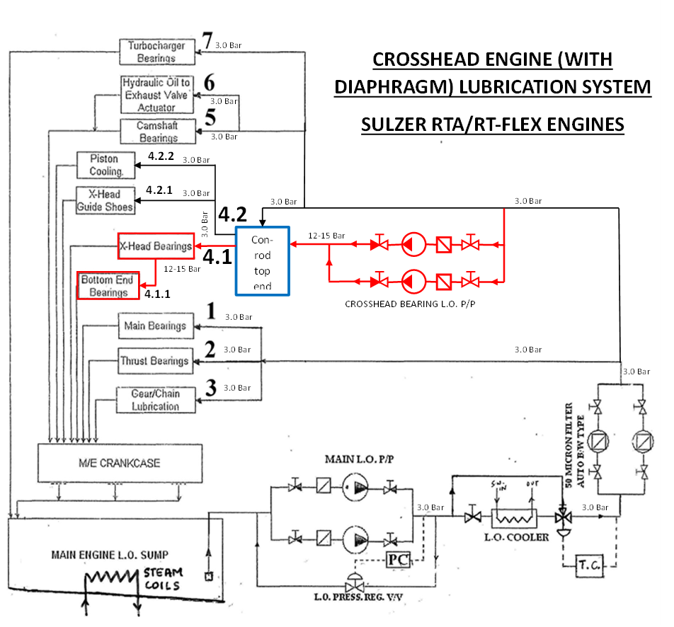
As discussed earlier, Sulzer engines have an additional booster pump for crosshead lubrication. The same has been demonstrated in the above image.
Authored by: C/E Shishir Dutt
Extra First Class Marine Engineer