The Previous Module
In this module, we will discuss the layout of a typical FWG plant of the evaporation type. (Btw, why did we mention evaporation type specifically? Are there any other types of FWG?)
Let us help you in building a prototype of FWG in your imagination, so that you can understand the upcoming modules better.
Layout
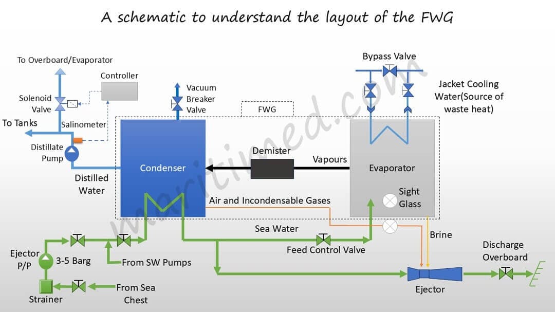
A typical FWG layout on a Merchant vessel consists of the following:
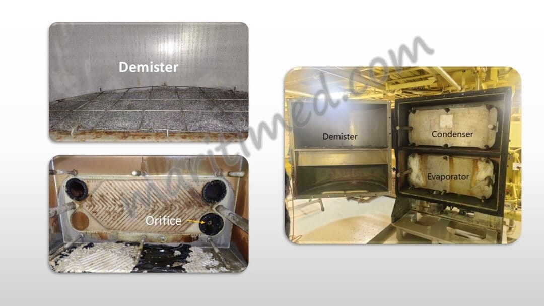
- FWG: includes shell, evaporator, Demister, and condenser
- Brine Ejector with NRV
- Air Ejector with NRV
- Ejector pump: S.W. supply to evaporator, Brine and air ejector, condenser cooling
- Distillate Pump: Transfer generated distilled water to Distilled Water/F.W. tanks
- Salinometer: Stops the Distillate pump discharge to the distill water tank when salinity exceeds the set point (>10 ppm). In some designs, the discharge is sent either overboard or back to the feed by activating a solenoid valve.
- Distilled water flow meter
- Valves
- Scale inhibitor System (Vaptreat injection system)
Please note that the Condenser, Evaporator, and demister are in a single unit called FWG.
Now, it’s time to understand the above layout.
JCW Line
The Jacket cooling water provides the heat needed for the FW production process. When the FWG is shut, the bypass is fully open. When the FWG needs to be put in operation, the inlet and outlet valves of the JCW to the FWG are open, and the bypass valve is slowly shut to force the JCW to flow through the evaporator. Please note that the amount by which this bypass valve should be shut depends on the shell temperature.
SW Line
The Ejector pump takes suction from the sea chest through a strainer and discharges it to the FWG at a pressure of around 3-5 bar. The SW first enters the condenser, where it has a cooling effect. After the condenser, the SW is sent to the ejector and the evaporator through a feed control valve. Partial Evaporation takes place in the evaporator, and the remaining SW washes away the salts formed after evaporation. This solution is called brine and is ejected overboard with the help of the brine eductor-cum-air ejector. The SW from the condenser outlet acts as a motive fluid for this eductor-cum-ejector device, thus creating a vacuum at the neck.
Why is the pressure at the discharge of the Ejector Pump mentioned specifically?
Although the values may differ depending on the design of the manufacturer, this value is considered to be the most usual one seen in the industry. Well, if this pressure is lower, the SW, which also acts as the motive fluid for the ejector-cum-eductor won’t be able to create a sufficient vacuum, which btw should be a minimum of 90%. On this note, having a higher pressure should have helped in the vacuum creation- then why have an upper limit? It is because- higher the pressure, higher the stress on the gasket joints.
Now, let’s take a look at the SW that got evaporated in the evaporator section. The water vapors generated pass through a demister, which is basically a wire mesh filter to catch fine water particles being carried away with the vapors. After this, vapours reach the condenser, they are cooled to form distilled water. This is the turning point where the SW transforms itself and starts its journey as FW.
FW Line
The distillate pump takes suction from the condenser and discharges the distilled water to either the distilled water tank(for boiler feed, etc) or the FW tanks through a mineralizer and sterilizer. A salinometer is fitted on the discharge piping of the pump which senses the salt content in the produced FW. If it is higher than the set limit by the user, the controller opens the solenoid valve and redirects the water back to the evaporator or overboard in some designs.
Sight Glass? Sight Glass!
Two sight glasses- Hmm, what do they do? Why are they important? The sight glass fitted at the bottom of the evaporator is an indication of the feed rate. If the brine is near the bottom of the sight glass, it means that the feed rate is too less for that evaporation rate and may result is heavy salt formation in the plates or carryover of salts with the vapours. If the brine is at the top of the sight glass, it means that the feed is too high for that evaporation rate and may result in lower production rates.
The feed control valve is then used to adjust the feed rate. Ideally, the brine level should be at the middle of the sight glass.
The other sight glass fitted on the air ejector line is an indication of the condensation process. Initially, nothing would be visible through this sight glass as air would be passing through. When sufficient vapors are condensed, the bottom of the condenser starts filling up with distilled water. After it overfills, the water starts appearing in the sight glass. This is an indication for the user to start the distillate pump.
Bonus
There is a flow-control orifice at the inlet of the SW to the evaporator, besides the feed control valve.
See you in the next modules :)
The Next Module