In arc welding, the source of heat is an electric arc. Arc welding is the most widely used and economical method of joining metal components/ pieces. This method requires a suitable electrode, low-voltage current source, cables, and a workpiece.
Heat Generation
The Workpiece is attached to a cable and the electrode to another. An electric arc is struck between the workpiece and the electrode as a large current jumps across the small gap between the two producing large amounts of heat. When an arc is struck between the electrode and workpiece, a flow of electrons takes place from the cathode to the anode. These electrons travel at a very high speed and strike the workpiece. A lot of kinetic energy of the moving electrons is converted into heat on impact. At the same time positively charged ions travelling from anode to cathode form a protective shield to flowing electrons.
About two-thirds of the heat energy produced is at the anode and the remaining one-third is at the cathode in all DC systems. In AC source of electricity for forming an arc the heat is equally distributed between the anode and the cathode. Thus, in arc welding heat is produced by electrical energy.
Electrodes help in this process. These are long thin rods of metal/ graphite. An arc is established by striking the tip of the electrode against the workpiece and withdrawing it quickly to maintain a small gap to maintain the arc. It produces temperatures of above 3500 deg. It is sufficient to melt the tip of the electrode and the workpiece. The electrode is moved down and forward at a constant speed as it is consumed to complete the weld. Electrodes used for arc welding are generally coated. The coating works as flux. This coating melts while welding and gives a gaseous shield around the molten metal pool to protect it from atmospheric oxygen. As the flux melts a part of it mixes with impurities in the molten metal pool causing them to float on top of the weld. This mixture of flux and impurities on cooling forms a protective layer on the weld.
Different Polarity Settings
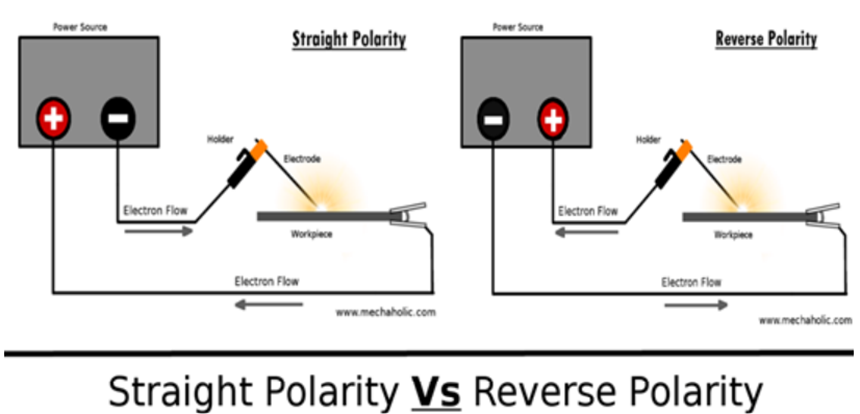
1. Reverse Polarity: While using a DC power source, if the workpiece is made negative terminal and electrode positive, the welding setup is said to be reverse polarity. Two third of the heat is generated near the positive terminal while one-third is generated near the negative terminal. As a result, thin pieces can be put at the cathode and welded by reverse polarity setup.
2. Straight Polarity: When a DC power source is used, if the workpiece is connected to the positive terminal, and the electrode is connected to the negative terminal- the setup is called straight polarity. It is used for welding thick sections as more heat is generated in the metal to be joined.
In the case of using an AC source of electricity for generating heat, we see that an equal amount of heat is generated at both ends. For obtaining a sound weld it is essential to select proper operating conditions - current, voltage, and speed of welding. A low current will give less penetration whereas a high current will cause excessive spatter and irregular deposits. High welding speed will result in less metal deposit and smaller beads resulting in weaker joints. On the other hand, slow speed will result in more penetration and overlapping of weld beads.