Fresh Water Generator or FWG is a machine/setup used onboard to produce fresh water from seawater. Before diving into the basics, let us go through a situation first.
Situation- You are on an island somewhere in the middle of the sea.
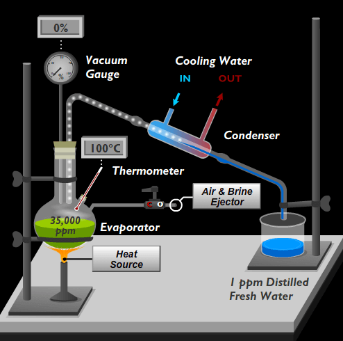
For survival, you will need at least food and water. Let's discuss water here. How do you think you will be able to produce water? If you have watched Discovery Channel- you would probably answer this. So, you would take some seawater in a pot/utensil and would heat it enough to cause boiling of the seawater. As the seawater starts boiling, the water vapors start to rise. You channel the vapors through some bamboo to your bottle. As the vapors cool down, you will have some water to drink in your bottle. That's how you will produce water on a deserted island.
The above seems quite obvious, right?
Analogy
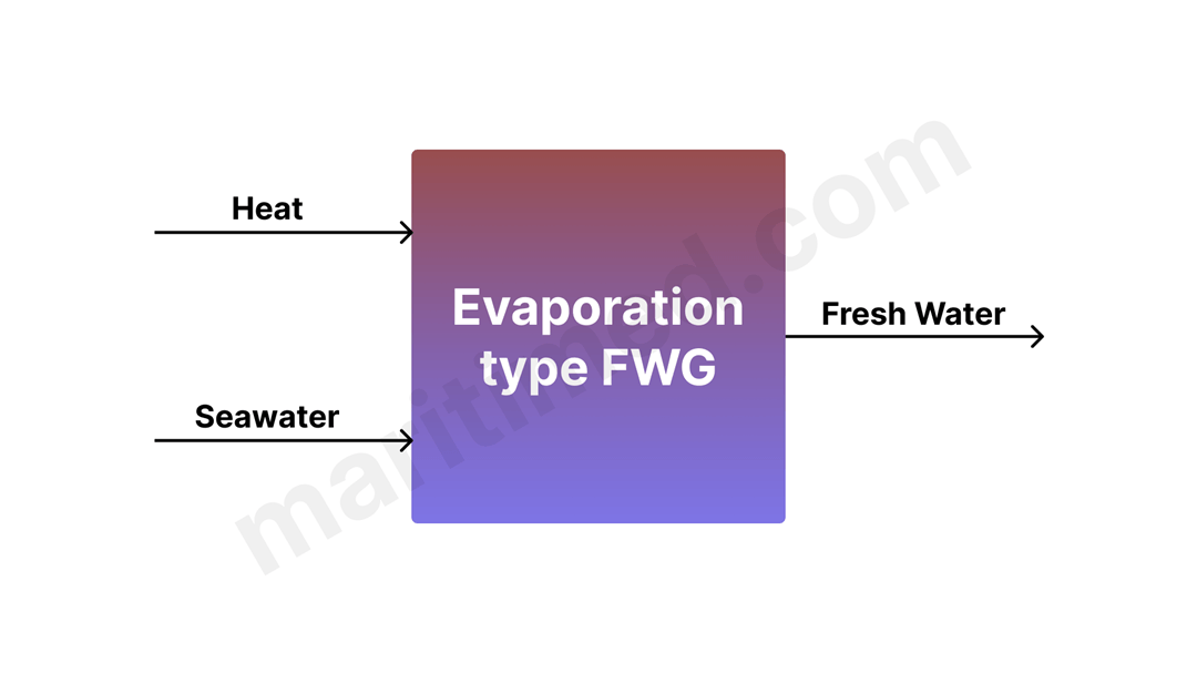
Something similar happens in most of the freshwater generators onboard.
So, to produce FW, we need SW and heat- which by the way is available in abundance onboard. As for heat, ships have plenty of waste heat which has to be dumped into the sea because of the operational and material limits. One such major source of operational waste heat is the Jacket Cooling Water(JCW) of the Main Engine onboard. Thus, FWGs onboard use JCW to heat the SW to produce water vapors.
Before we even think of cooling the vapors to the liquid state, we have a challenge to overcome. We all have learned that the boiling temperature of water is 100 deg C. On the other hand, the JCW temperatures onboard range from 70-90 deg C. Additionally, the boiling point of water increases with the increase in salinity. What should be done now?
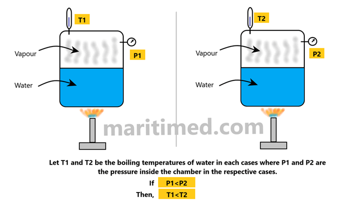
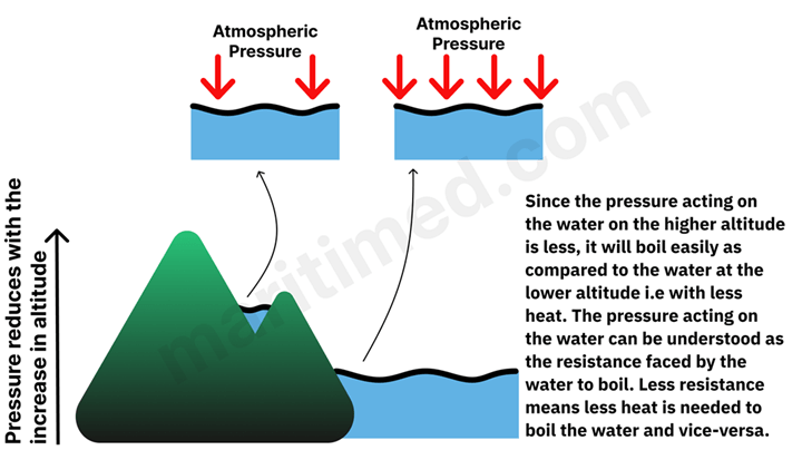
You will get the answer if you revisit what we learned in our school- “The boiling point of water is 100 deg C at atmospheric pressure.”. As the pressure being exerted above the water is reduced, the boiling point of water reduces. So, if the pressure in the chamber (where the water is boiled) is reduced, even the JCW of 80 deg C would be sufficient to produce vapors.
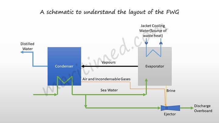
Now, let’s think about cooling the vapors. Can the SW be used to cool the vapors? Well, yes. Refer to the diagram below.
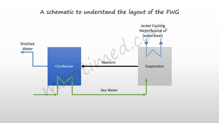
For ease of understanding, we have shown the FWG in blocks. The SW acts as a cooling medium while it passes through the condenser, where it condenses the vapours generated by extracting their latent heat, while it’s own temperature rises. This temperature rise of cooling SW heats it up by a few degrees. Thereafter, this preheated SW enters the evaporator, where due to low pressure of the evaporator shell, it gets converted into steam.
Will the complete quantity of seawater sent to the evaporator turn into vapors?
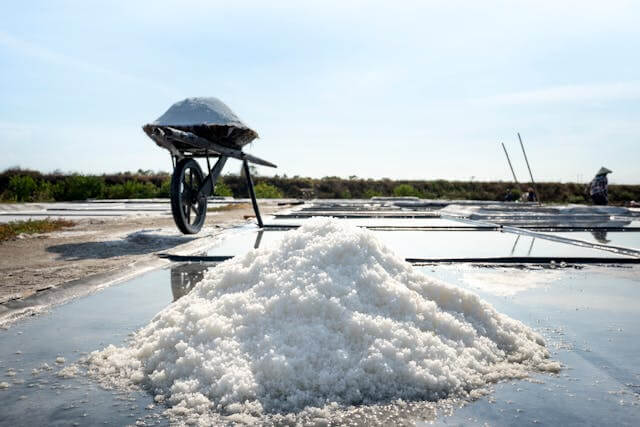
No. Before we dive into this, we want you to revisit what we learned in our school- How is salt made from seawater? Referring to the below image, the sea water is allowed to collect in the small areas and then it is left in the sun for drying. Once the water evaporates, the salt remains.
Now you know what happens inside. If we allow the complete amount of seawater to evaporate into steam/vapors, salt deposits will build up on the evaporator tubes/plates, further deteriorating the heat transfer. This is the reason why the seawater is always sent in copious amounts so that only partial evaporation takes place and the salt gets washed down with the remaining seawater available. This solution is often called brine and needs to be discharged overboard.
How is the vacuum created inside the FWG?
To create a vacuum inside the FWG, first of all, we need to ensure that the FWG is air-tight which means there is no opening via which it is connected to the open atmosphere. The FWG enclosure is made air-tight using gaskets and there is only one mounting which connects the enclosure to the atmosphere- Vacuum breaking valve. When this valve is closed, the enclosure is airtight. We will discuss the mountings and parts in detail in the upcoming modules. After the air-tightness is achieved, the air already present inside the FWG needs to be removed. Can you think of ways to achieve this?
Well, what if we told you that SW itself can create a vacuum inside the FWG? Seems confusing? Not anymore.
The system uses something called as air ejector and a brine eductor, both of which work on the Venturi effect, based on Bernoulli’s principle. When a liquid stream is passed through an ejector or eductor, a vacuum is formed at the neck on the ejector.
Ejector: When the device is used to pump gas/air or create vacuum then it is generally called as an Ejector. The motive fluid can be high pressure liquid or a gas.
Eductor: When the device is used to pump a liquid from one point to another, it is called an Eductor. Eductors can be used for pumping chemicals, stripping remaining cargo, bilge pumping or for emtying tanks prior cleaning. The motive fluid is generally high pressure liquid.
Parts of an ejector
The ejector mainly consists of three parts- The Convergent nozzle, the neck, and the divergent nozzle.
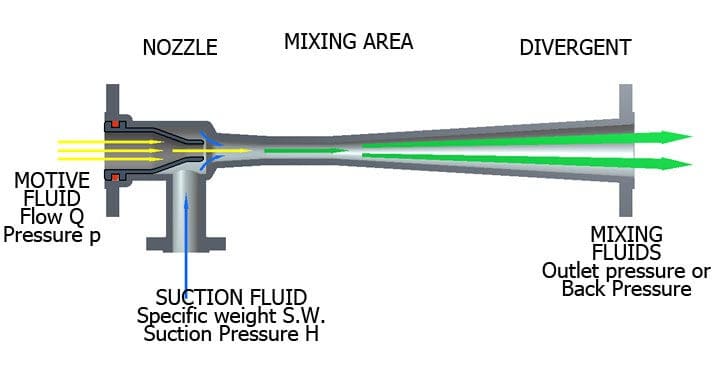
Working Principle of Ejector/Eductor
As the motive fluid passed through the convergent nozzle; due to reduction in the cross-sectional area; the flow velocity increases and hence the pressure drops, there by creating vacuum which creates a suction affect. Thereafter motive fluid passes through a constant area section known as the “neck”. The neck is connected to the fluid being sucked through a suction or a dip tube. The pressure reduction at the end of the convergent nozzle is sufficient to maintain vacuum in the neck area which maintains “suction lift” in the suction tube/pipe. However, if the fluid sucked into the neck area is not pumped out, there will be stagnation no pressure and suction effect will be lost. There comes the role of Divergent nozzle. The mixture of motive fluid and the sucked fluid moves through divergent nozzle, where the flow velocity reduces, thus increasing the pressure. This increase in pressure is responsible for creating the discharge head and causes the fluid to overcome the pipe friction of the gravitational head and fluid mixture is hence discharged.
In the case of FWG:
Two pipes are attached to the neck of the ejector, to suck the air to create vacuum and the other one to discharge brine (you forgot about the brine, didn’t you?).
The Next Module of this Machinery